Overview
In the multi-storey automated car parking facility integrated within the Robot Park Tower in Sharjah, vehicles are transported using specialized steel-wire suspended robot holding trays. Because vehicles vary in weight and rarely possess a true center-of-mass, asymmetric wire stretching occurs during hoisting operations. This uneven deflection prevents the tray from docking properly into the ports cleanly.
The robot park is split into two different independent robot systems coined as the twin shuttle robot park, to solve this issue on the first hoisting bay, Robot 1 was equipped with the original smart levelling system designed by Senior Automation Engineer Moatasem Al Zoubi. However, the second robotic bay remained unassisted, facing the same mechanical instability.
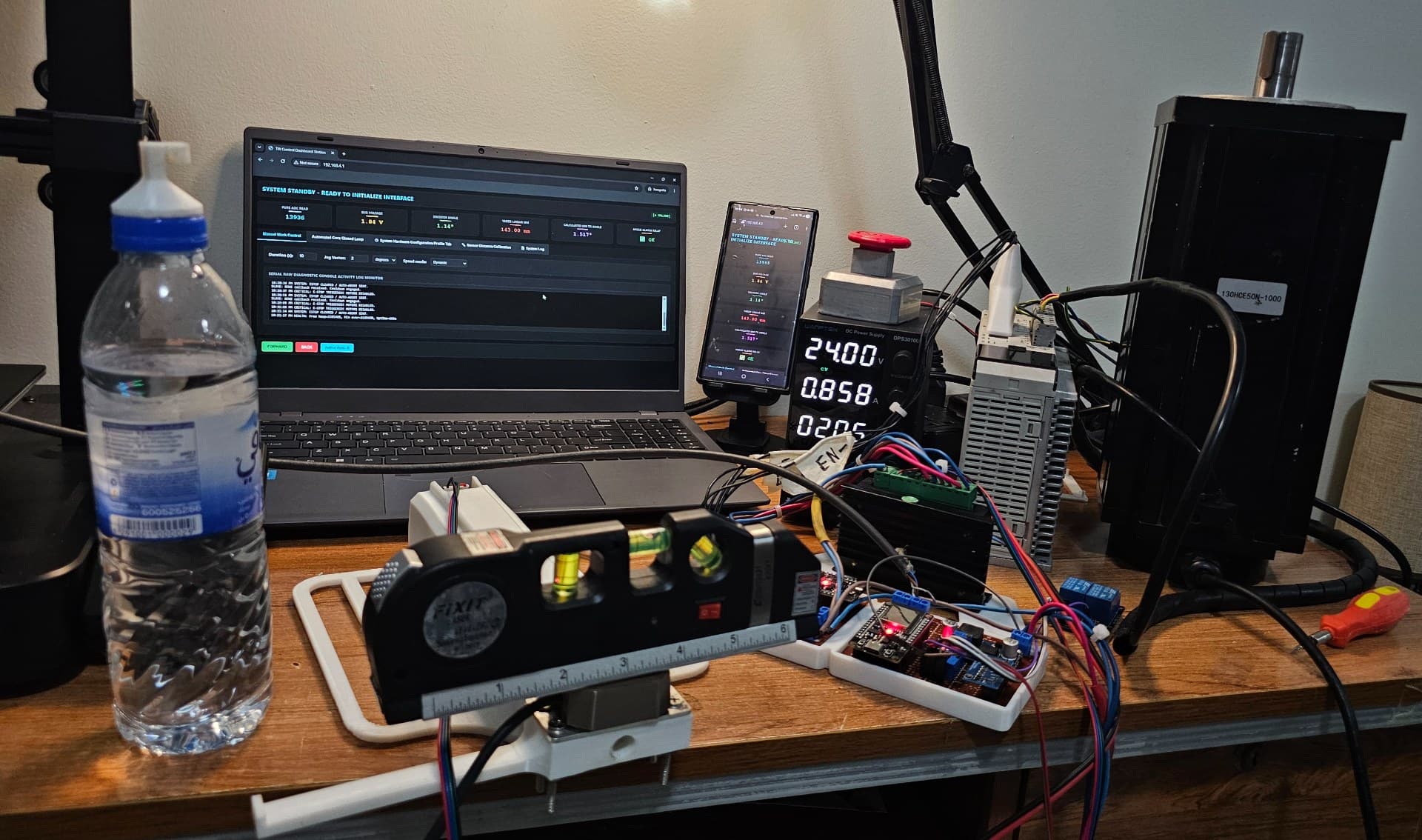
As a mechatronics pre-engineer, I was tasked with designing and deploying an independent, secondary control architecture to resolve the challenge on Robot 2. Taking a distinct tactical and hardware approach, the Precision Angle Correction System was developed and implemented as the Smart Levelling System to continuously sense tray angular tilt and automatically correct tilt error via dynamic lifting mechanisms, guaranteeing a perfectly level platform during precision docking.
Sensor processing, filtering, and correction calculations take place on a dedicated Master ESP32, while motion commands are dispatched asynchronously via low-latency 2.4GHz wireless transmission to a Slave Motor Driver ESP32.
Key achievements include engineering a dual-stage signal pipeline incorporating a tuned two-stage Kalman filter (), designing signal conditioning circuitry to interface with industrial 0–10 V instrumentation using low-voltage microcontrollers, resolving mechanical gear train backlash, deploying a web interface with integrated safety interlocks, and achieving an electrical and mechanical precision & repeatability of ±0.01°, significantly exceeding the factory SICK TMM22E specification of the industrial sensor.
Technical Architecture & Circuit Design
Power Distribution & Precision Analog Front-End
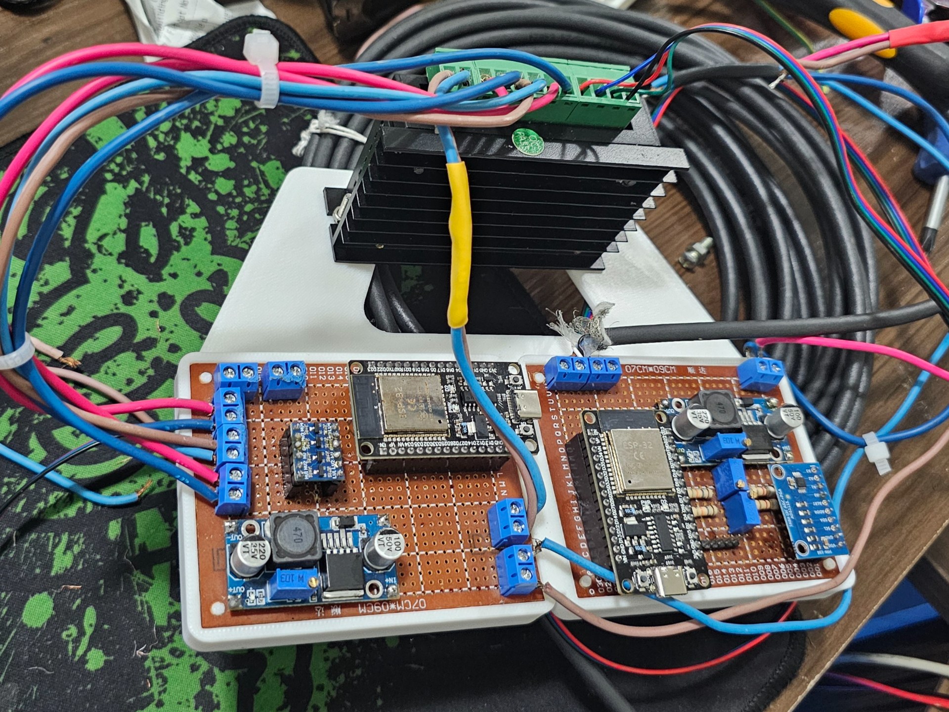
- Power Regulation: An LM2596 buck converter steps down the 24V main power bus to a stable 5V DC rail for both the Master and Slave ESP32 logic modules. The ADS1115 receives its power directly from the 3.3V line of the Master ESP32, ensuring I²C data lines operate natively at 3.3V with zero logic-level mismatch.
- Analog Signal Conditioning: The SICK TMM22E-PLH010S55 industrial tilt sensor outputs dynamic angular telemetry as a 0–10V analog signal. To map this safely to the 0–3.3V microcontroller ingestion range, a precision dual-resistor voltage divider featuring multi-turn trimmer potentiometers was engineered.
- Potentiometer Calibration: Multi-turn precision potentiometers fine-tune resistor divider ratios, eliminating baseline shift and input voltage drift.
- Analog-to-Digital Conversion: Processed signals pass to an external ADS1115 16-Bit ADC over I²C, completely bypassing the non-linear, noisy internal ADC of the ESP32 to achieve sub-millivolt sampling precision.
Tech Stack
Embedded Systems & Core Algorithms
- Auto-Orientation & Control Engine: Custom C++ state machine executing two-phase reverse kinematic leveling (Phase 1 coarse angular stroke Phase 2 fine edge millimeter alignment).
- Stability Window & Gating Logic: Time-based stability hold window engine that locks motion phases only after sensor telemetry settles within defined tolerance bounds, preventing dynamic hunting and mechanical overshoot.
- Dynamic Configuration Management: Dynamic LittleFS JSON profile parser (
config.json) enabling real-time calibration parameter switching (NEMA 17 prototype vs. NEMA 52 production) without firmware recompilation. - Signal Filtering Pipeline: High-speed 16-sample moving average window buffer coupled with a tuned dual-stage Kalman filter () for sub-arcdegree noise suppression.
- Safety & Interlock Engine: Software auto-abort fault boundaries triggering local isolation relays alongside hardware E-stop motor interlocks.
- Hardware Task Watchdog Timer (WDT): System health monitoring (
esp_task_wdt.h) with diagnostic boot reason logging () to track power loss or unexpected resets.
Hardware & Electronics
- Microcontrollers: 2 × ESP32 Development Boards (Master Control & Slave Motor Driver communicating via 2.4GHz ESP-NOW peer-to-peer protocol targeting Slave MAC
F4:65:0B:E9:03:8Cwith packedstruct_motionpayloads). - Primary Tilt Sensor: SICK TMM22E-PLH010S55 Industrial Dual-Axis Inclinometer (0 – 10 V).
- Analog Front-End & ADC Watchdog: ADS1115 16-Bit Precision ADC via I²C with input voltage divider network ( mapping). Features raw ADC bounds checking (
43.0–25020.0) and a 30-second stale-data I²C health watchdog that automatically re-initializes the bus if data hangs. - Safety Interlock Pins:
- GPIO 13 (
ESTOP_PIN): Hardwired debounced emergency stop input switch (DEBOUNCE_DELAY_MS = 50ms). - GPIO 14 (
ANGLE_ALARM_RELAY_PIN): High-power relay output energized when tilt error exceedsAUTO_ABORT_ANGLE_LIMIT.
- GPIO 13 (
- Power Delivery & Regulation: 2 × LM2596 DC-DC Buck Converter modules for stable bus rails ().
Signal Processing & Mathematical Pipeline
Raw inclination data undergoes multi-stage digital filtering prior to generating motion execution steps.
Filtering & Geometric Transformation
- Moving Average Buffer: A 16-element rolling window dampens electrical noise, and transient mechanical vibrations caused by tray movement.
- Deflection Calculation: The averaged angular reading () is transformed into a physical linear deviation () at the edge of the tray:
- Dual Kalman Filter: Filter parameters (, ) smooth residual process noise without introducing extreme phase delays into the correction loop.
Autocorrection Control Algorithm & Motion Profiles
The autocorrection engine continuously evaluates live angular readings () and filtered edge deviation () against dynamic profile parameters loaded from config.json:
- Orientation Tolerance: Acceptable deadband threshold (
ANGLE_ORIENTATION_WINDOW/MM_ORIENTATION_WINDOW) within which no further motor moves are triggered. - Stability Window & Hold Duration: Allowed fluctuation bounds (
ANGLE_STABILITY_WINDOW/MM_STABILITY_WINDOW) that sensor telemetry must continuously maintain for a designated hold time (ANGLE_HOLD_TIME/MM_HOLD_TIMEseconds) before motion execution locks in. - Stroke Fraction Scaling:
ANGLE_STROKE_FRACTIONmultiplier (default0.9/ 90%) applied to stroke calculations to prevent dynamic overshooting during high-inertia platform moves. - Dual-Speed Profiles: Independent maximum step rates for Phase 1 rotation (
FAST_ANGLE_SPEED) vs Phase 2 precision positioning (SLOW_MM_SPEED). - Auto-Abort Boundary: Critical safety boundary (
AUTO_ABORT_ANGLE_LIMIT) beyond which automatic feedback terminates and trips the GPIO 14 relay output.
Closed-Loop State Machine Lifecycle
The Master ESP32 executes an asynchronous 6-stage state machine that governs closed-loop feedback:
STANDBY: Loop Disengaged— Executive engine disengaged; monitoring telemetry without triggering motor moves.STABILIZING ANGLE— Checks if live angular fluctuation remains withinANGLE_STABILITY_WINDOW. Must hold stable forANGLE_HOLD_TIMEseconds before initiating Phase 1.INITIATING ANGLE MOVE— Calculates Phase 1 stroke steps, formats an ESP-NOWstruct_motionpacket, and dispatches the move to the Slave driver atFAST_ANGLE_SPEED. Clears the stability history window and enforcesPOST_MOVE_WAIT_TIME.STABILIZING MM— Engages the 16-sample rolling buffer and dual-stage Kalman filter pipeline (). Checks if linear millimeter fluctuation remains withinMM_STABILITY_WINDOWforMM_HOLD_TIMEseconds.INITIATING MM MOVE— Calculates Phase 2 fine millimeter stroke steps and dispatches the move to the Slave driver atSLOW_MM_SPEED.CLOSED LOOP CONVERGED— Triggered when residual tilt and linear deviation fall withinMM_ORIENTATION_WINDOW. The controller enters a tared zero-state until external forces disrupt tray stability.
Two-Phase Correction Execution
Motion execution relies on a dual-stage profile tailored to high-inertia mechanical systems:
- Phase 1 (Coarse Angle Movement): Large, rapid steps pull the platform out of gross angular tilt.
- Phase 2 (Fine Linear Movement): Precision millimeter-scale adjustments align the tray flush with landing dock guides.
Reverse Kinematic Execution Pipeline
The algorithm executes motion through two distinct phases, both resolving to vertical millimeter stroke displacement at the lifting mechanism before mapping to motor step pulses:
-
Phase 1: Coarse Angular Error Screw Stroke (mm) Fast Step Execution
-
Low-Latency Coarse Drive: Phase 1 uses raw inclinometer rotational error () directly. By bypassing the heavy cascaded Kalman filter pipeline, it eliminates phase delay and stabilization lag, allowing the controller to execute rapid, high-speed corrections for large tilt errors.
-
Screw Displacement Calculation: Maps through the physical leverage radius
pivot_to_rope() to determine the exact linear displacement needed at the lifting screw:
-
-
Phase 2: Fine Millimeter Alignment (High Precision / Noise Suppression)
-
Filtered Telemetry Engine: Once gross inclination error is resolved, Phase 2 engages the 16-sample rolling averager and dual-stage Kalman filter pipeline to suppress structural vibration and sensor noise before executing sub-millimeter positioning.
-
Angular Reconstruction: Reads target alignment edge error () measured at radius
pivot_to_edge() and reconstructs the true residual tilt angle:
-
Step Calculation & Geometric Offset Mapping
To convert inclination readings and calculated edge deviations into precise stepper motor pulses, the control algorithm maps mathematical outputs through a reverse kinematic model.
Because the primary tilt sensor is an inclinometer, its physical mounting location along the tray frame is independent, as it measures true rotational tilt () regardless of position. The step generation math depends on two structural leverage dimensions loaded dynamically from the active JSON profile:
-
pivot_to_rope (): Horizontal distance from the pivot axis to the lifting screw/rope mechanism.
-
pivot_to_edge (): Horizontal distance from the pivot axis to the outer tray edge where flush alignment must be achieved.
Prototype vs. Production Kinematics
Both the Prototype Profile (Direct Pivot Drive) and the Production Profile (Offset Screw Mechanism) execute a two-phase correction routine (Phase 1 for coarse angle adjustment, Phase 2 for fine millimeter positioning). However, each processes the kinematic transformation differently based on its mechanical configuration and JSON profile parameters:
-
Small-Scale Prototype Profile (Direct Pivot Drive): In the initial prototype, the stepper motor was directly coupled to the pivot axis without an offset lifting screw mechanism (). Motion mapped directly to rotation at the pivot shaft:
- Phase 1 (Coarse Angle):
Phase 1: Coarse Angle Translation ()
- Rope Linear Resolution ():
- Equivalent Angular Resolution ():
- Phase 1 Target Step Calculation:
Phase 2: Fine Millimeter Translation ()
In Phase 2, when working with residual linear offset error () measured at , the master controller reverses edge deflection back into angular space, calculates vertical displacement at the lifting rope (), and outputs exact motor pulses:
- Edge Deflection to Angular Error:
- Calculated Vertical Displacement at Rope:
- Phase 2 Target Step Calculation:
Prototyping & Calibration Evolution
Prototype Phase (NEMA 17)
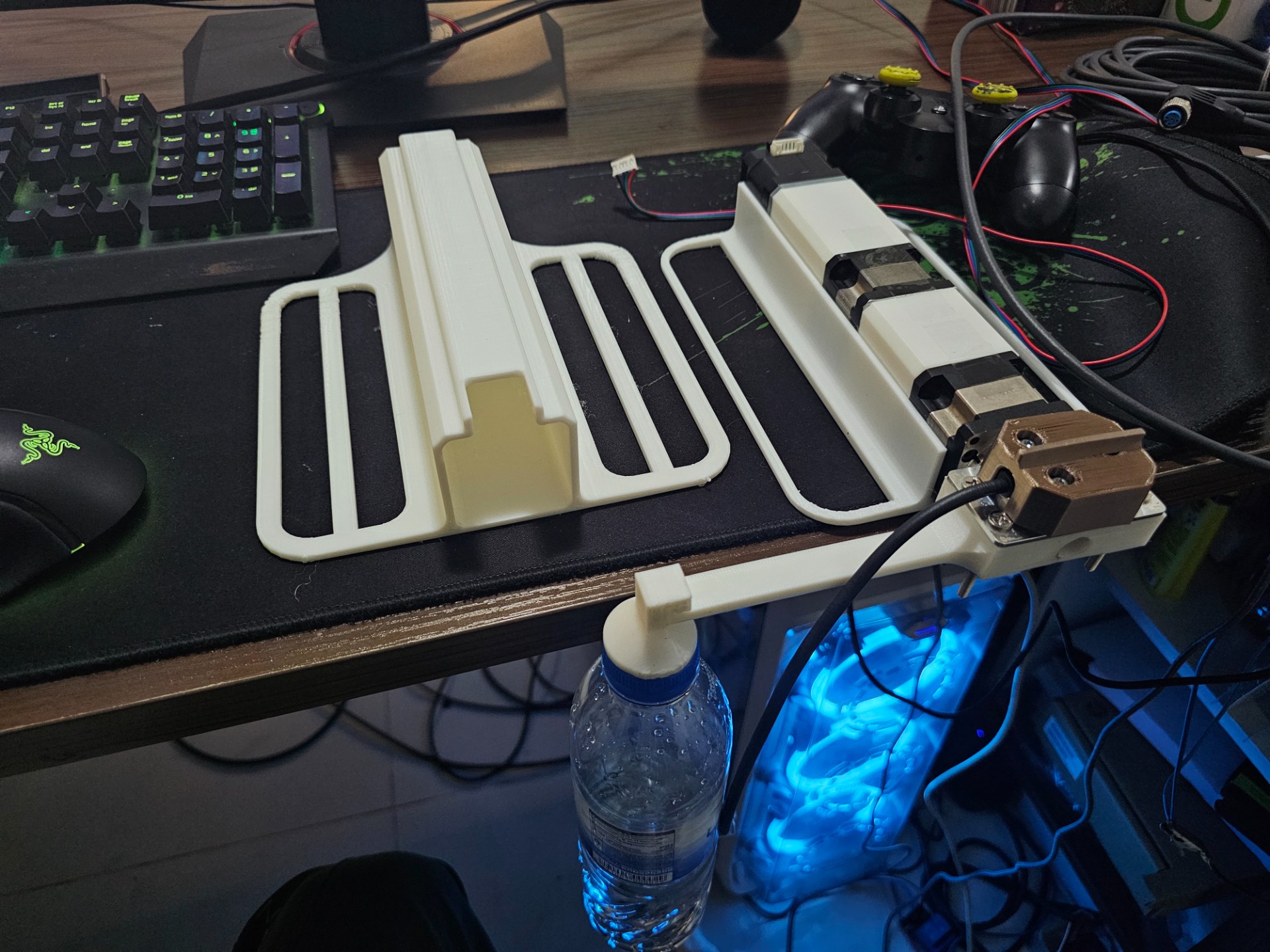
Initial design validation took place on a scaled mechanical frame utilizing NEMA 17 stepper motors, custom 3D-printed mounting brackets, and a hand-soldered prototype board for clean, low-noise signal distribution.
To achieve maximum angular resolution and high output torque without sacrificing positioning accuracy:
-
Compound Gear Reduction: The NEMA 17 motor drives through a primary planetary gearbox, which is subsequently coupled in series to and gear stages. This compound configuration yields a final overall mechanical reduction ratio of 1020:1.
-
Full-Step Execution & Precision: The motor driver was intentionally configured with no microstepping (full-step operation). Relying entirely on high-ratio mechanical gear reduction rather than fractional microstep holding current guaranteed maximum step repeatability, eliminated magnetic detent slipping under load, and provided deterministic mechanical positioning.
Production Deployment & NEMA 52 Scaling
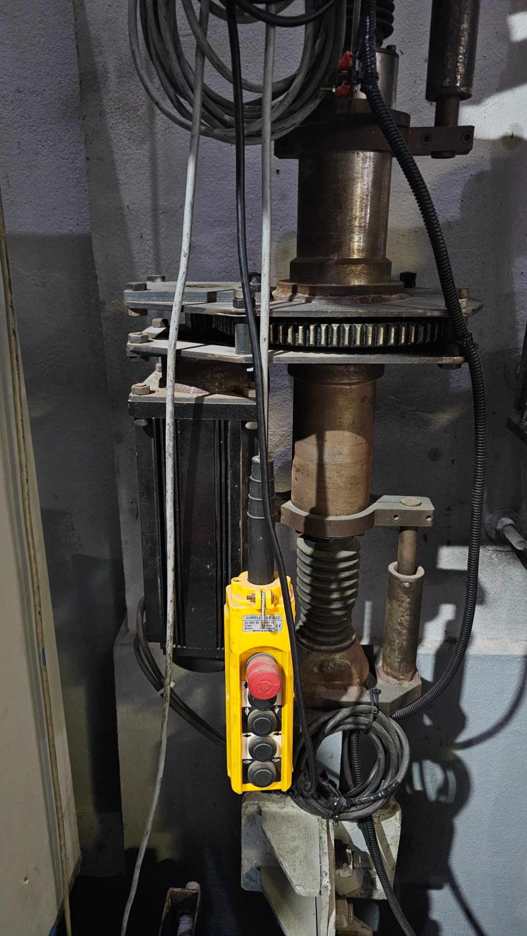
After establishing sensor stability on the prototype, calibration constants were scaled up for full-size installation using high-torque NEMA 52 stepper motors. Kinematic math parameters were adjusted directly on the actual Robot 2 park structure to ensure docking performance under live payload distributions.
Safety Systems & Web Interface
The system incorporates hardware fault isolation alongside interactive software controls.
Safety Interlocks
-
Auto-Abort Boundary & Hardware Safety Relay (GPIO 14): If angular deviation exceeds
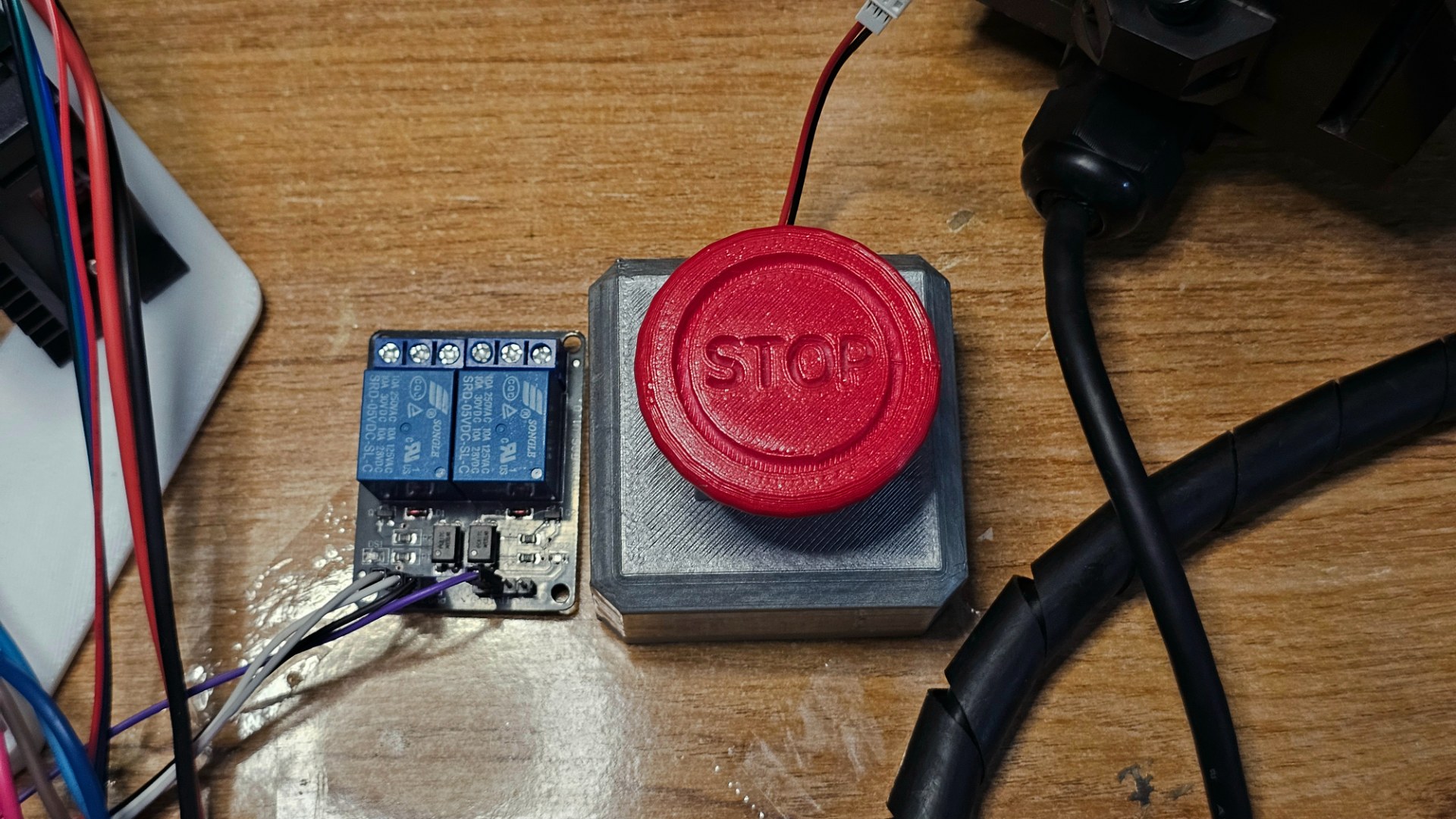
AUTO_ABORT_ANGLE_LIMIT(configurable, e.g. ), the Master ESP32 immediately disengages the automatic feedback engine. Simultaneously, it energizes the GPIO 14 relay output (ANGLE_ALARM_RELAY_PIN), triggering local isolation relays to alert maintenance technicians and physically isolate hardware actuators. -
Dedicated Hardware Stepper E-Stop (GPIO 13): A hardwired emergency switch on GPIO 13 (
ESTOP_PIN) continuously monitored by a 50ms software debouncing state machine (DEBOUNCE_DELAY_MS). Toggling the switch instantly disengages power to the motor drivers and dispatches emergency halt packets via ESP-NOW (is_estop = 1), stopping physical actuation instantly without clearing signal processing logs or resetting telemetry state. Recovery features configurable toggle-to-reset rules and a safety cooldown timer (ESTOP_RESET_COOLDOWN).
Web Management Dashboard
The Master ESP32 hosts an asynchronous HTTP Web Server (WebServer on Port 80) backed by an internal SPI Flash File System (LittleFS). The interface provides low-latency telemetry streaming, closed-loop state control, dynamic parameter tuning, and persistent log inspection across 5 dedicated web dashboard tabs.
Real-Time Telemetry Banner & Header Grid
At the top of the interface, a live 6-card telemetry grid polls hardware status every 500ms:
- Pure ADC Read: 16-bit raw counts from the ADS1115 ADC (
0–25020valid range) monitored by an ADC health watchdog. - Bus Voltage: Scaled analog input voltage ( front-end signal).
- Encoder Angle: Live computed tilt angle ().
- Tared Linear MM: Filtered linear deviation () in millimeters, processed through a 16-sample moving average buffer and a two-stage Kalman Filter (, ).
1. Manual Work Control
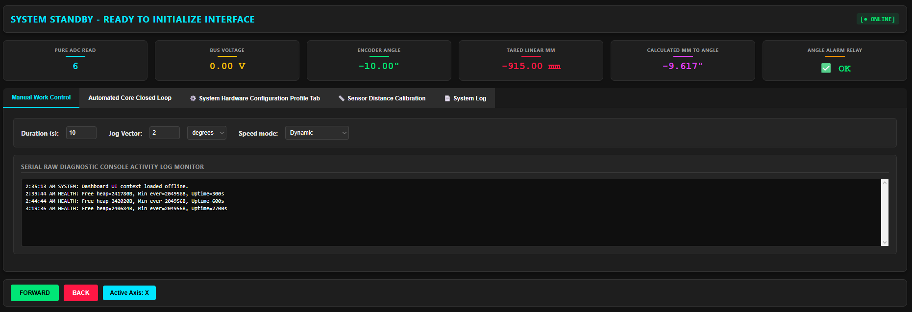
The Manual Work Control tab allows operators to perform direct manual override and jog actuation without engaging feedback loops:
- Jog Vector & Unit Selection: Command step movements specified in
degrees,mm, or rawsteps. - Speed Mode Control:
- Dynamic Mode: Automatically uses profile-defined fast/slow speeds (
FAST_ANGLE_SPEED/SLOW_MM_SPEED). - Static Mode: Allows custom fixed step-rate overrides (e.g.,
800 steps/s).
- Dynamic Mode: Automatically uses profile-defined fast/slow speeds (
- Duration Safeguards: Configurable manual motion window timeout (default
10s). - Serial Diagnostic Console: Embedded live terminal console displaying low-latency system events, ESP-NOW packet transmissions, and raw hardware diagnostics in real time.
2. Automated Core Closed Loop
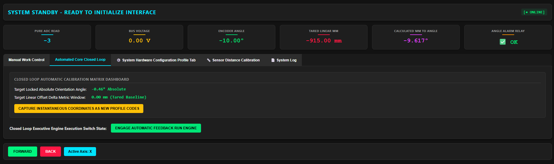
The Automated Core Closed Loop tab serves as the executive control panel for the two-phase feedback engine:
- Target Coordinate Management: Displays the active Target Locked Absolute Orientation Angle () and Target Linear Offset Delta Metric Window (tared to ).
- Instantaneous Coordinate Capture: One-click baseline calibration button (
capture_ori) captures current live sensor readings and saves them as the new zero-reference target coordinates in flash memory. - Feedback Engine Control: Toggle button (
toggle_loop) to engage or disengage the closed-loop state machine. - Live State Machine Status: Displays real-time phase indicators (
STANDBY,STABILIZING ANGLE,INITIATING ANGLE MOVE,STABILIZING MM,INITIATING MM MOVE,CLOSED LOOP CONVERGED).
3. System Hardware Configuration Profile Tab
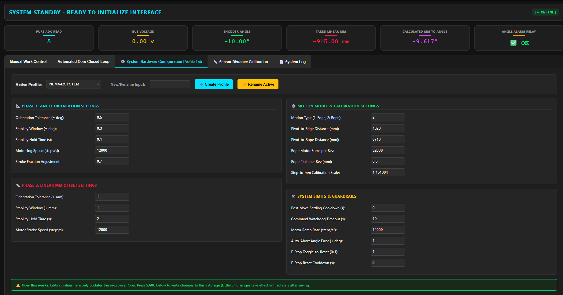
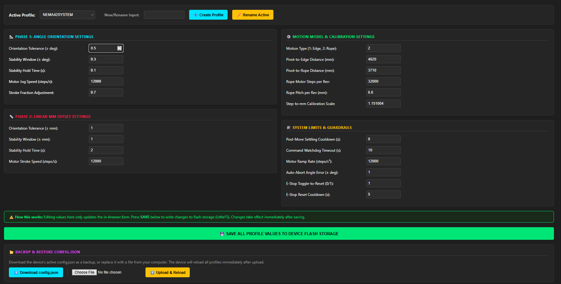
The System Hardware Configuration Profile tab provides full runtime parameter tuning and JSON profile management without requiring firmware recompilation:
- Profile Management: Dynamically switch between predefined profiles (
NEMA17SYSTEMprototype vsNEMA42SYSTEM/NEMA52production), create new profiles, or rename active profiles. - Phase 1: Angle Orientation Settings:
ANGLE_ORIENTATION_WINDOW: Orientation convergence tolerance ().ANGLE_STABILITY_WINDOW: Allowed fluctuation threshold before triggering move ().ANGLE_HOLD_TIME: Required settling duration before executing stroke ().FAST_ANGLE_SPEED: Primary rotation motor speed ().
4. Sensor Distance Calibration
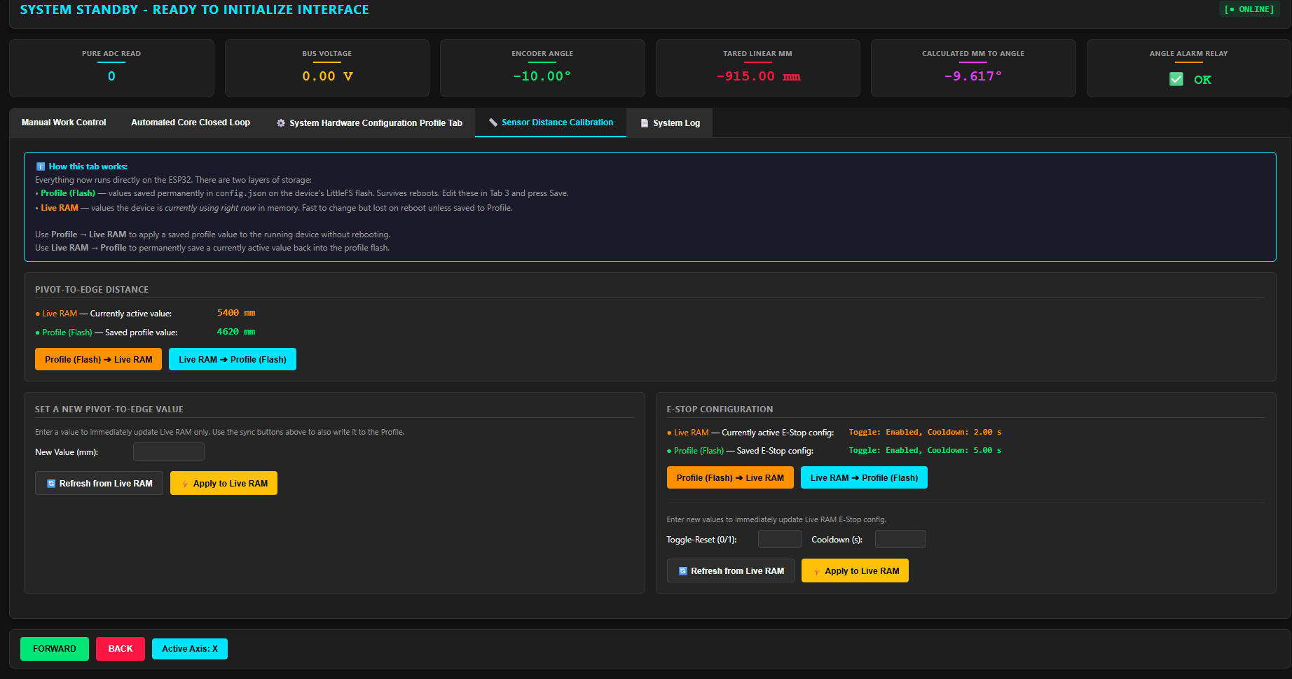
The Sensor Distance Calibration tab manages real-time RAM vs. Flash memory synchronization:
- Dual-Layer Memory Architecture:
- Profile (Flash): Persistent settings saved in
config.jsonon LittleFS flash (survives reboots). - Live RAM: In-memory values currently active in the running control loop (fast to modify).
- Profile (Flash): Persistent settings saved in
- Pivot-to-Edge Distance Synchronization:
- Side-by-side view comparing Live RAM vs. Flash Profile values.
- One-click sync buttons: Profile ➔ Live RAM (apply without reboot) and Live RAM ➔ Profile (permanently write live adjustments to flash).
- Live input field to adjust on the fly.
- E-Stop Configuration Tuning: Live RAM vs. Profile inspection and instant tuning of E-Stop reset behavior and recovery cooldown timers.
5. System Log
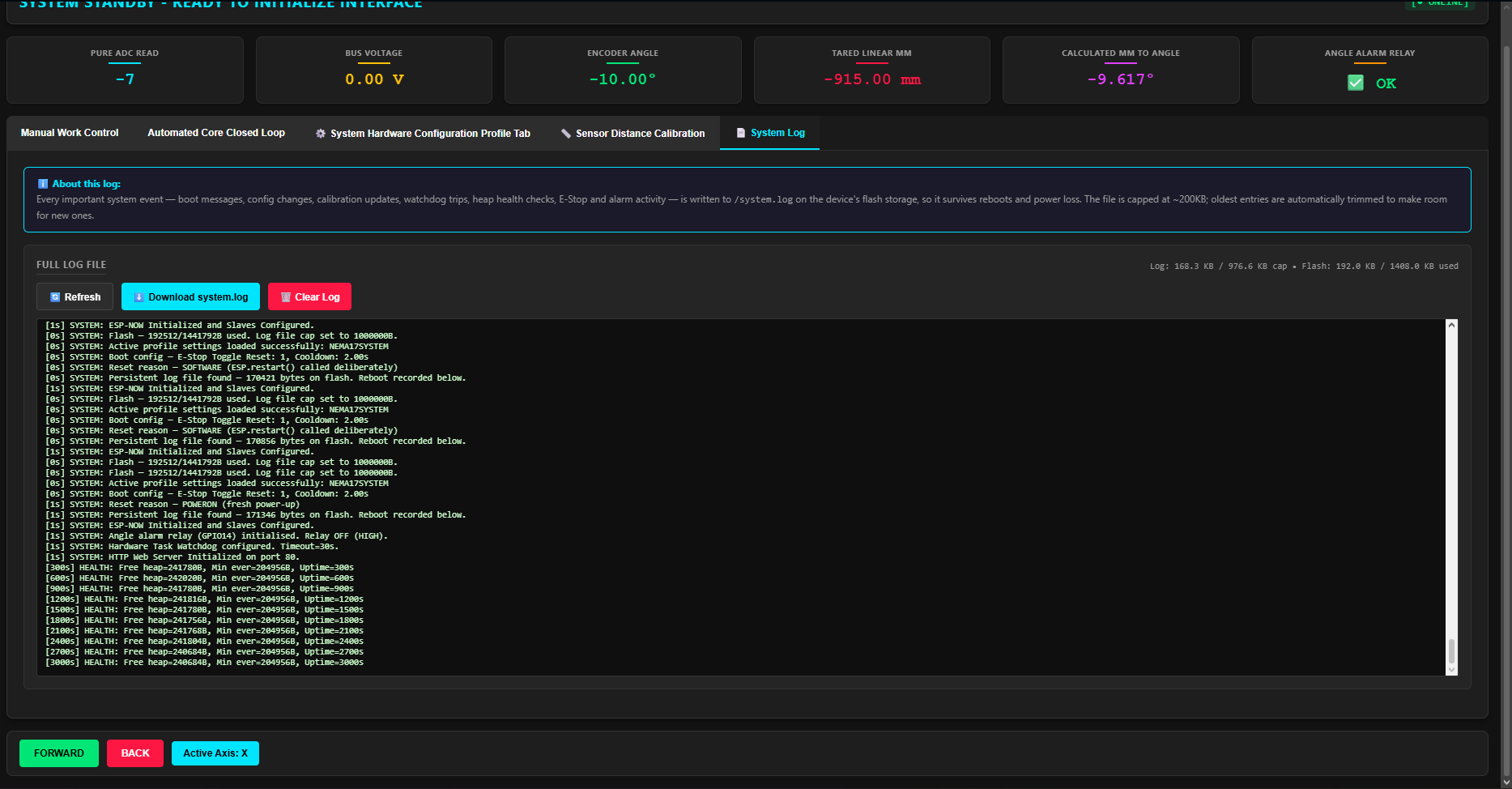
The System Log tab provides persistent diagnostic auditing for hardware inspection:
- Persistent Flash Storage (
/system.log): Automatically records timestamped logs of all system events—including boot reasons (esp_reset_reason()), ESP-NOW packet receipts, ADC health checks, Kalman filter resets, E-Stop toggles, and watchdog alerts—to LittleFS flash storage so logs survive power cycles. - Automatic Ring Buffer: Capped at (
LOG_FILE_MAX_BYTES); automatically trims oldest log entries down to (LOG_FILE_TRIM_TO_BYTES) when full to prevent SPI flash overflow. - Log Controls: Live terminal log viewer featuring one-click Refresh, Download
system.log, and Clear Log functions.
System Roadmap & Future Multi-Node Architecture
The current deployment operates as a 2-Node Peer-to-Peer control loop designed to validate single-axis stabilization on one corner of the parking tray frame.
To achieve full 3-D spatial leveling across the entire vehicle platform, the system architecture is designed to scale to a 4-Node Distributed Network:
- Distributed Telemetry Generation: Three independent ESP32 sensor processing nodes mounted at key perimeter locations continuously calculate local inclination telemetry.
- Central Kinematic Aggregation: A master motor controller collects all three high-speed ESP-NOW data streams, evaluates the platform's multi-axis tilt plane, and compensates for dynamic center-of-mass shifts caused by varying vehicle payloads.
- Synchronized Tri-Corner Actuation: The central driver executes real-time reverse kinematic step calculations across all three stepper actuators simultaneously, ensuring the vehicle platform remains level during lift and docking sequences.